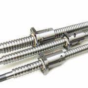
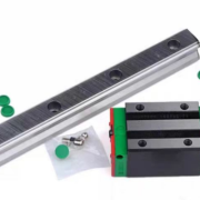
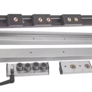
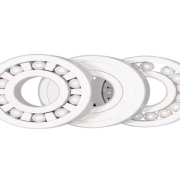
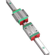
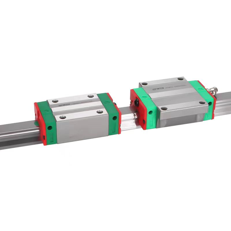
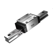
THK linear guide THK LM linar guide

THK Linear Guide LM Types

THK Linear Guide Types
THK is a well-known brand in the field of linear motion products, and its linear guide systems are widely used in various industries. The THK linear guide series offers a range of types to meet different application needs.

LM guide

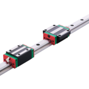
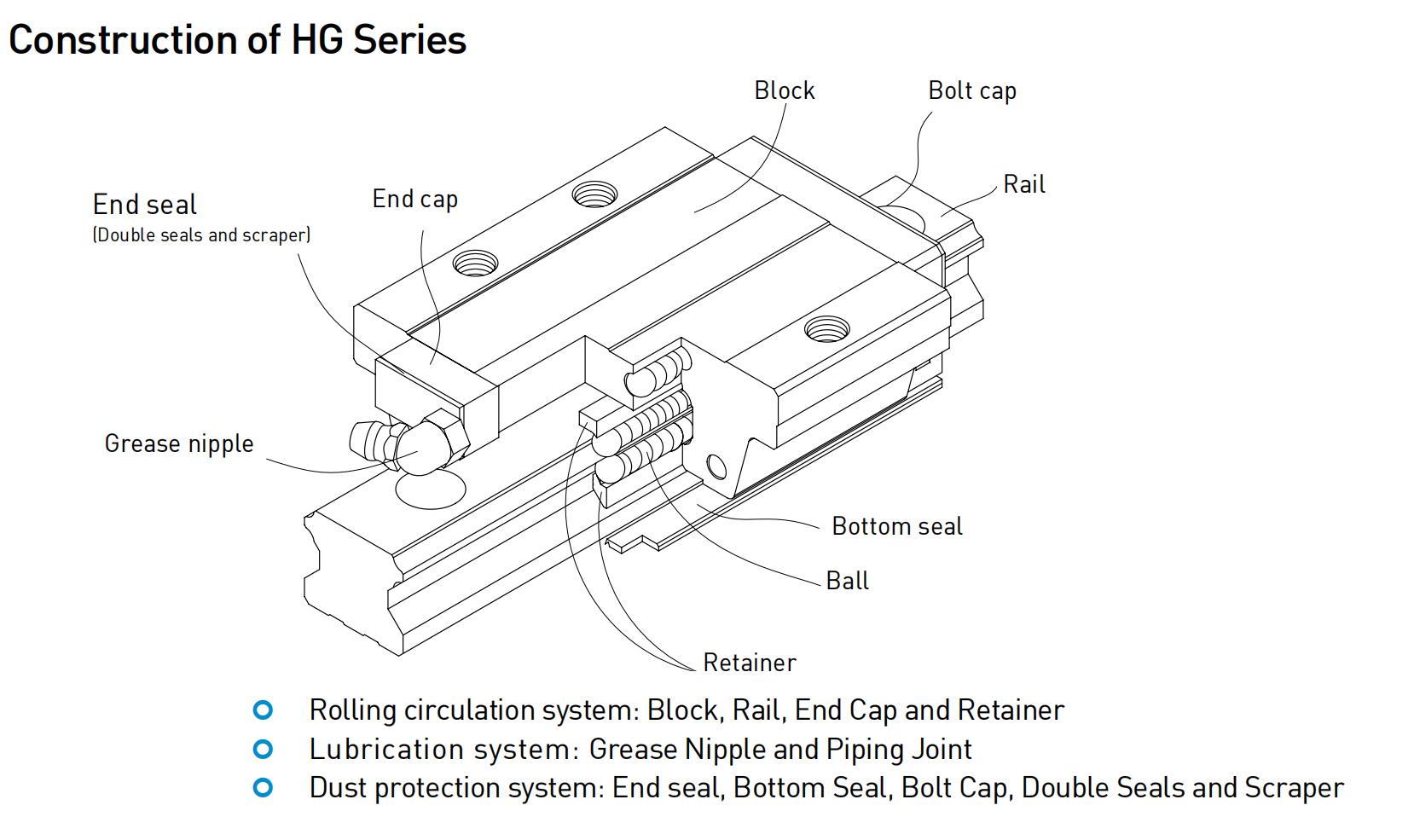
One of the most popular types of THK linear guides is the LM guide. LM guides are widely used in industries such as manufacturing, automation, and robotics. These guides provide smooth and accurate linear motion, ensuring high precision in applications. The unique patented ball circulation structure of LM guides guarantees smooth movement and excellent rigidity. They are available in different sizes and load capacities to suit different requirements.
The key features of the LM guide series is its versatility. It can be used in both horizontal and vertical orientations, allowing for flexibility in design and installation. The modular design of the LM guides also makes them easy to assemble and disassemble, simplifying maintenance and replacement.

THK LM guides are designed to withstand heavy loads and provide long service life. The precision-ground raceways and balls ensure smooth and accurate movement, reducing friction and wear. This results in extended operating life and reduced downtime for maintenance.

The LM guide series also offers options for different levels of precision. THK provides standard LM guides for general-purpose applications, as well as high-precision LM guides for applications that require exceptional accuracy. The high-precision LM guides are designed with tighter tolerances and reduced clearance, ensuring precise linear motion.

THK offers LM guides with different types of ball circulation systems. These include the End Cap type, which provides increased rigidity and stability, and the Interchangeable type that allows for easy replacement of components.

THK linear guide have may models,Global Standard Size Model SHS, Caged Ball LM Guide Radial Type Model SSR, Models SHS-LC / SHS-LCM, Models SHS-LR / SHS-LRM, Models SHS-LV / SHS-LVM.

THK Linear Guide: Empowering Diverse Industries with Precision Motion Control
The versatility of THK Linear Guide extends far beyond its exceptional performance in precision motion control. This groundbreaking linear motion system has found wide application across a diverse range of industries, providing unparalleled benefits and enhancing operational efficiency.

In the robotics industry, where precise and fluid movement is crucial, THK Linear Guide plays a vital role. It enables robots to achieve accurate and smooth linear motion, facilitating intricate tasks such as pick-and-place operations, assembly, and packaging. With its superior accuracy and repeatability, THK Linear Guide ensures robots can perform tasks with precision and reliability, ultimately increasing productivity and reducing errors.

THK LM guide rails are widely used in various mechanical equipment. THK guide rails are of excellent quality and cheap. It can better reduce industrial use costs. Various types of guide rails serve different industrial purposes.

Areswin Precison Machinery Company is  leader supplier of all kinds of linear guide, ball screw, bearings,spline,support unit and other motion products. With reliable supply chain system and high-quality service,Areswin can provide customers with various industrial transmission products.OEM service can also peovided.

Areswin Precison Machinery Company supply THK all kinds of lienar gudie. If you need please contact us, we will give you a good feedback.Contact Us – ARESWIN (aresmotion.com)

In summary, THK LM linear guide types are widely recognized for their exceptional performance, precision, and reliability. With their patented ball circulation structure, modular design, and versatile orientation options, THK LM guides offer smooth and accurate linear motion for various industrial applications. Whether it is for high-speed, high-load, or high-precision requirements, THK provides a comprehensive range of LM guide types to meet the diverse needs of different industries. Trust in THK to deliver top-quality LM linear guides that exceed expectations.

What Are The Advantages Of Automatic Application Of Ball Screw In Intelligent System?

With the rapid development of science and technology, intelligent systems are gradually infiltrating into various industries and becoming the key force to promote the productivity of modern industry. In this transformation, the ball screw pair has become the core transmission component in the intelligent system with its excellent performance and diversified advantages. It can not only significantly improve the performance and efficiency of automation system, but also bring unprecedented changes and innovations to modern industrial production.

The application and importance of ball screw pair in intelligent system, we need to master its basic principle and structure. Ball screw pair is an efficient transmission device, and its core lies in the ball transmission mechanism between screw and nut. This mechanism not only ensures high transmission efficiency and excellent rigidity, but also provides precise positioning ability, which makes it widely used in many automation equipment and mechanical systems. In the intelligent system, the ball screw pair has the following obvious advantages:

Ball screw pair stands out with its excellent precision and rigidity, and becomes the key to precise control in intelligent system. In the intelligent system, the precise requirements for position and strength are extremely high, and the ball screw pair just meets this demanding requirement. Its high-precision positioning ability and excellent rigidity not only ensure the stability and reliability of the system, but also greatly improve the working accuracy and efficiency of the system, which provides strong support for the outstanding performance of the intelligent system.

With its high transmission efficiency, the ball screw pair shows remarkable advantages in energy utilization in intelligent systems. In intelligent systems, improving energy efficiency is the key to reduce operating costs. Because of the ball transmission mechanism, the ball screw pair has higher transmission efficiency than the traditional thread transmission, which can not only effectively reduce energy consumption, but also reduce the operating cost of the system, which provides strong support for the sustainable development of the intelligent system.

With its long service life and convenient maintenance process, the ball screw pair is unique in the intelligent system. Especially on the equipment that needs long-term continuous operation, the ball screw pair shows excellent stability and reliability. Its spare parts loss is very small, and its service life is long, which greatly reduces the downtime and maintenance time of the system, thus effectively reducing the maintenance cost. This feature provides a solid guarantee for the continuous and efficient operation of the intelligent system and ensures the stability and continuity of the production process.

The ball screw pair shows excellent high-speed movement and large load transmission ability in the intelligent system. In automation equipment, the requirements for fast and accurate positioning and heavy load transmission are extremely high, and the ball screw pair can easily meet these requirements with its excellent performance. This not only improves the working efficiency of the system, but also significantly improves the production efficiency, which provides a strong support for the rapid development of intelligent systems.

Ball screw pair has outstanding performance in the automation application of intelligent system, and its advantages are remarkable. Excellent precision, rigidity and transmission efficiency ensure the stability and efficient operation of the system. The long service life and simple maintenance process of the ball screw pair also provide a solid guarantee for the continuous operation of the system. High-speed movement and large-load transmission capability further improve the performance and efficiency of automation equipment and inject new vitality into modern industrial production.

Because of these unique advantages, the ball screw pair has become an indispensable core component in the intelligent system, which continuously promotes the innovation and development of automation technology. With the continuous progress of technology, we have reason to believe that the application prospect of ball screw pair in intelligent system will be broader, which will bring more far-reaching influence and benefit to the modernization transformation of various industries and help the upgrading and transformation of global industrial production.

How to prevent dust on linear guide rail

How to prevent dust on linear guide rail and how to solve the problem of dust blocking slider?

How to prevent dust on linear guide rail and how to solve the problem of dust blocking slider?

Dust prevention is the most important part when using linear guide rail system. If dust and other foreign matter enter the back of the linear guide rail, it will cause abnormal wear and shorten the service life. Therefore, it is necessary to choose a sealing device or a dustproof device that meets the requirements of the use environment when dust and other foreign objects are expected to invade.

(1) Special sealing gasket for linear motion system In order to improve the dustproof ability, sealing gaskets made of special synthetic rubber with high wear resistance, as well as accessories such as (laminated contact scraper, etc.) and cleaning rings are provided in each linear guide rail system.

(2) Special telescopic dust cover In places where the use environment is harsh, some models are equipped with special soft retractable dust cover and special dust cover.

Please refer to the corresponding optional accessories (dust-proof) items of various products for details and descriptions of sealing gasket markings. In addition, when it needs to be used in an environment that is easily affected by cutting chips and cutting fluid splashing, it is suggested to use a soft circular telescopic cover to protect the whole system, or use a large telescopic dust cover. When the product is used, the dust will block the installation hole. What method can be used to remove it? Foreign matter may enter the slider after blocking the installation hole. In this case, we suggest installing an internal sealing gasket on the slider. In this way, the entry of foreign bodies and the erosion of water can be well prevented. For some models, it can be installed from bottom to top, so that there is no installation hole on the upper surface of the guide rail.

lm

Dust-proof, Waterproof and Anti-corrosion Treatment Technology of Linear Guideway

Linear guide rail is an important part of mechanical transmission components, which is widely used in aviation manufacturing, machining, automation equipment and other fields. However, the linear guide rail is often affected by dust, moisture, corrosion and other factors in the use process, thus affecting its service life and performance. Therefore, in order to improve the reliability and durability of linear guide rail, dustproof, waterproof and anti-corrosion treatment technology has become an important link in the manufacture and application of linear guide rail.

First, the dustproof treatment technology of linear guide rail During the operation of linear guide rail, it will be disturbed by a large number of impurities such as dust and sand in the environment, thus affecting its stability and accuracy. Therefore, dust prevention technology has become an important link in the manufacture and application of linear guide rail. Sealing structure design: the sealing structure design of linear guide rail is the primary key to dust prevention. Manufacturers need to adopt different sealing structure design schemes according to the use environment and working requirements of linear guide rail. Common seal structure design includes rubber seal, metal seal, cover seal and so on. Surface treatment: the surface treatment of linear guide rail is also an important part of dust prevention. Through surface treatment, the surface of the linear guide rail can be smooth and flat, thus reducing the adhesion of dust and impurities. Surface treatment techniques include grinding, polishing and electrochemical polishing. Coating treatment: coating treatment is also one of the important technologies for dust prevention. By coating a dustproof coating on the surface of the linear guide rail, the adhesion of dust and impurities can be effectively reduced. Commonly used dust-proof coating materials include PTFE, polyethylene, polypropylene and so on.

Second, the waterproof treatment technology of linear guide rail During the use of linear guide rail, it will be disturbed by moisture, which will affect its operation effect and life. Therefore, waterproof treatment technology has become an important link in the manufacture and application of linear guide rail. Sealing structure design: the first step of waterproof treatment is sealing structure design. Manufacturers need to adopt different sealing structure design schemes according to the use environment and working requirements of linear guide rail. Common seal structure design includes rubber seal, metal seal, cover seal and so on. Waterproof coating treatment: Waterproof coating treatment is also one of the important waterproof technologies. By coating a waterproof coating on the surface of the linear guide rail, the penetration of water can be effectively prevented. Commonly used waterproof coating materials include polyurethane, polyurethane-fatty acid ester, epoxy resin and so on. Material selection: Material selection is also one of the important waterproof technologies. Manufacturers need to choose waterproof materials to make linear guide rails. Commonly used materials include stainless steel, aluminum alloy, plastic and so on.

Third, the anti-corrosion treatment technology of linear guide rail

The linear guide rail will be disturbed by corrosion in the process of use, which will affect its operation effect and life. Therefore, anti-corrosion treatment technology has become an important link in the manufacture and application of linear guide rail.

Anti-corrosion coating treatment: Anti-corrosion coating treatment is one of the important anti-corrosion technologies. By coating an anticorrosive coating on the surface of the linear guide rail, corrosion can be effectively prevented. Commonly used anticorrosive coating materials include fluorocarbon paint, baking paint and epoxy resin. Material selection: Material selection is also one of the important anti-corrosion technologies. Manufacturers need to choose materials with corrosion resistance to manufacture linear guide rails. Commonly used materials include stainless steel, aluminum alloy, plastic and so on.

Surface treatment: Surface treatment is also one of the important anti-corrosion technologies. Through surface treatment, the surface of linear guide rail can be smooth and flat, thus reducing the occurrence of corrosion. Surface treatment techniques include grinding, polishing and electrochemical polishing.

In a word, the dustproof, waterproof and anticorrosion treatment technology of linear guide rail is an important link in the manufacture and application of linear guide rail. Manufacturers need to adopt different treatment technologies according to the use environment and working requirements of linear guide rail, so as to improve the reliability and durability of linear guide rail. The maintenance technology of linear guide rail is very important for the service life and performance. Regular cleaning, regular lubrication, regular inspection, avoiding overload and vibration are common maintenance techniques. In addition, regular calibration, maintenance records and regular replacement are also important maintenance contents. Different linear guides need different maintenance technologies, so different maintenance technologies need to be adopted before use, so it is necessary to know and plan them before use. By adopting proper maintenance technology, the reliability and durability of linear guide rail can be improved, thus meeting the needs of different fields.

What is the machining process of linear slider?

Linear slider is a general component to complete accurate feed motion and complex multi-station work cycle motion. According to the technological requirements of the workpiece, it can be equipped with perceptual power components to complete drilling, reaming, boring, tapping, chamfering, scraping the end face, etc. It can input the coordinates of linear motion and has the characteristics of accurate movement. It is suitable for rain-proof, dust-proof and wind-proof of conveyor belts in power plants, cement plants, coal mines and other major mining enterprises, which reduces the loss of goods during transportation, makes the conveyor belts safer and more reliable in operation, and plays a greater role in purifying the environment.

Sliding table machining process and assembly process are two main contents of mechanical manufacturing technology research. The process of changing the shape, size, relative position and properties of the production object in the production process to make it a finished product or a semi-finished product is called a technological process. For example, blank manufacturing, machining, heat treatment and assembly are all technological processes. Production process and technological process.
The production process of products refers to the whole process of turning raw materials into finished products. The production process of mechanical products generally includes:

1. Preparation of linear slider production and technology, such as process design, design and manufacture of special process equipment, preparation of production plan, preparation of production materials, etc.

2. Manufacture of linear slider blank such as casting, forging, stamping, etc.

3. Machining, cutting, heat treatment and surface treatment of linear slider parts;

4. Assembly of linear slider products, such as assembly, assembly, debugging and inspection, painting, etc.

5. linear slider production services such as the supply, transportation and storage of raw materials, purchased parts and tools; In the process, if the shape, size and surface quality of the production object are directly changed by mechanical processing, it will become a process of qualified parts, which is called mechanical processing process.

Similarly, the process of assembling the processed parts into machines to achieve the required assembly accuracy and obtain the predetermined technical performance is called assembly process.

TBI ball spline

Introduction to ball splines/TBI ball spline

Introduction to ball splines

The ball spline is a bearing that can provide smooth and unrestricted linear motion. The ball spline is made up of steel balls in the inner cavity of the spline mother (sleeve) that roll back and forth on the groove of the spline shaft to achieve linear motion. Precision orientable linear transmission components.


Ball splines are transmission parts commonly used in ZR axis motion on high-precision precision instruments. Its main function is to synchronize precise positioning rotation with linear motion. It is a light-load linear transmission component with high precision, high speed and low friction. , small finished product size, widely used in various high-inspiration automatic equipment and devices with high reliability requirements, such as semiconductor packaging, mounting equipment, medical equipment, etc.


Ball spline construction

Ball splines use balls installed in the spline sleeve (female) to circulate in precision-ground grooves on the spline shaft, while performing smooth linear rolling and transmitting torque. Ball splines and spline shafts are designed and processed with different numbers of grooves and different angles as contact points.


The spline mother is composed of six parts: the main bearing steel cavity, balls, plastic turning channels, dust covers, key pins, and screws. The cavity is made into different numbers of ball paths depending on the size, usually 2 or 4 rows. , 6 columns, the more the number, the better the accuracy.


Spline shaft: It is a high straightness optical axis that processes different mathematical grooves according to the corresponding number of spline mother steel ball rows. The higher the straightness and roundness, the higher the accuracy.


Different processing as above can achieve different torques and precisions. In addition to being highly sensitive, it also greatly increases the load capacity. It is suitable for environments that require high positioning accuracy and high-speed motion performance. In such environments where vibration and impact loads are too large It can also play an effective role. At the same time, when used to replace linear ball bushings, the rated load of ball splines is more than ten times that of linear bushings when the shaft diameter is the same, so the design can become very compact. It is safe to use and has high durability even under cantilever loads, moments, etc.


Ball spline classification

  1. Shape classification: straight ball spline, flange ball spline, slider type ball spline


  1. Integrated distinction: integrated ball spline, rotating nut ball spline


  1. Shaft diameter distinction: micro ball splines (light load and torque), large shaft diameter ball splines (medium and high load and torque)


  1. Stroke distinction: unlimited stroke ball spline, limited stroke ball spline


Areswin Precision Machinery Company can provide TBI ball spline. There are SLT ball splines and SLF ball splines all can supply.

Please check here for more information Ball Spline SLF Series/ flange design Ball Spline-ARESWIN (aresmotion.com)

thin section bearing

Introduction of thin section bearing

Introduction of thin section bearing


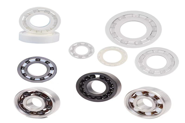
Thin section bearings are a type of ball bearing that has a compact design, which makes them suitable for use in applications where space is limited. They are characterized by their low profile, light weight, and high precision. Thin section bearings are used in a wide range of industries, including aerospace, robotics, medical, and semiconductor manufacturing.

Thin section bearing also called thin wall bearing

One of the primary benefits of thin section bearings is their compact design. They are much thinner than standard ball bearings, making them ideal for use in applications where space is limited. Their low profile allows for a more compact and efficient design, which can help reduce the overall size and weight of the equipment they are used in.

Another advantage of thin section bearings is their high precision. They are manufactured to very tight tolerances, which ensures that they can operate smoothly and reliably even at high speeds. The precise manufacturing process also means that they have a high degree of accuracy, which is essential for applications that require precise movement or positioning.

Thin section bearings are also known for their low friction and smooth operation. They are designed to reduce the amount of friction between the moving parts, which can help to increase the lifespan of the equipment they are used in. The low friction also means that they require less energy to operate, which can lead to lower energy costs.


Another benefit of thin section bearings is their versatility. They can be used in a wide range of applications, including robotics, medical devices, aerospace equipment, and semiconductor manufacturing equipment. Their compact design makes them ideal for use in applications where space is limited, while their high precision and low friction make them suitable for applications that require precise movement or positioning.

Thin section bearings can also provide cost savings over time. While they may be more expensive than standard ball bearings upfront, their compact design and high precision can help to reduce the overall size and weight of the equipment they are used in. This can lead to cost savings in areas such as transportation, storage, and installation.

In summary, thin section bearings are a type of ball bearing that has a compact design, high precision, and low friction. They are ideal for use in applications where space is limited and are commonly used in industries such as aerospace, robotics, medical, and semiconductor manufacturing. While they may be more expensive than standard ball bearings upfront, their compact design and high precision can provide cost savings over time.


Xi’an Areswin Precision Machinery Company can supply all kinds of thin section bearing, if you need please let us know.We will give you a solution for the your industry need.

How to install built-in double-axis linear guide rail?

Linear guide rails are essential components of many machines and systems, as they provide a smooth and precise movement for components such as tools, spindles, and slides. The installation of built-in double-axis linear guide rails requires careful planning and attention to detail, as any errors or misalignments can lead to reduced accuracy and performance.
The first step in installing a built-in double-axis linear guide rail is to choose the right rail and carriage assembly for your application. Factors such as load capacity, speed, and precision requirements will influence your choice of rail, as will the size and weight of the components being moved. It is essential to select a rail that is compatible with your existing equipment and that meets your specific performance requirements.

Once you have selected the appropriate rail and carriage assembly, you will need to prepare the mounting surface. The surface must be flat, level, and free of any debris or contaminants that could interfere with the installation or operation of the guide rail. It is also important to ensure that the mounting surface is strong enough to support the weight of the rail and any components that will be mounted on it.

Next, you will need to determine the placement of the guide rail and mark the mounting holes. This is a critical step, as the accuracy of the mounting holes will directly affect the alignment and performance of the guide rail. It is important to use precise measuring tools and techniques to ensure that the mounting holes are located in the correct positions.
Once the mounting holes have been marked, you can drill the holes and install the guide rail. It is important to use the correct size and type of screws or bolts to secure the rail to the mounting surface. It is also important to tighten the screws or bolts evenly and to the recommended torque specifications to ensure that the rail is securely and properly mounted.

After the guide rail has been installed, you will need to mount the carriage assembly. This is typically done by sliding the carriage onto the rail and securing it in place with screws or bolts. It is important to ensure that the carriage is properly aligned with the rail and that it moves smoothly and without any binding or interference.

Once the carriage assembly has been mounted, you can test the performance of the guide rail. This can be done by moving the carriage along the rail and checking for any misalignments or binding. If any issues are detected, it may be necessary to adjust the mounting or alignment of the rail and carriage assembly.

Areswin Precision Machinery Company can provide long life SGB double axis linear guide rail SGR10 SGR15 SGR20 SGR25 SGR35 With Slide Block SGB10 SGB15 SGB20 SGB25 SGB35. guide rail length customization,If you need, feel free to ask us for the product catalogue.

In conclusion, the installation of built-in double-axis linear guide rails requires careful planning and attention to detail. It is essential to choose the right rail and carriage assembly for your application, prepare the mounting surface properly, and carefully align and secure the rail and carriage assembly. With proper installation and maintenance, a built-in double-axis linear guide rail can provide reliable and precise movement for many years.

What is the difference between screw pitch and lead?

Lead-vs-pitch_Animate

Pitch

Pitch is the distance between screw threads and is commonly used with inch sized products and specified as threads per inch.

Lead

Lead is the linear travel the nut makes per one screw revolution and is how ball screws are typically specified.

For a single start thread, lead is equal to the pitch.  For multiple start screws the lead is the pitch multiplied by the number of starts.

What are the differences between rolled and ground ballscrews?

The difference between cold rolling screw (rolled screw) and grinding screw is as follows:
1. Different processing methods:
Cold-rolled ball screw is to cut grooves with a certain depth in polished rod material at first, and the groove spacing is equal to the wire spacing you want to process, and then roll them out with a rolling mill. On the basis of press rolling, the grinding screw uses a special cylindrical grinder to precisely process the arc groove with the same shape and size, and the cut groove is at the bottom of the arc groove.

Rolled ball screw is preferred over cutting (turning on a lathe) for lead screws. It involves pressing a round bar between a set of dies that roll the threads into it. It results in a harder surface with superior surface finish for lead screws. Rolled ball screw is also the most common process for ballscrews because it is more economical and sufficiently accurate for most industrial applications. Lead accuracy can be held to better than .003 inch/foot and longer lengths are possible than with ground ballscrews.

If higher accuracy is required, grinding should be considered. The grinding process can hold lead accuracy’s as tight as .0003 inch/foot or better. However, this process is much more expensive and the maximum length of screw is much shorter.

2. Different scope of application and cost:
The precision grade of rolling screw is below the average, which is suitable for ordinary equipment with low precision requirements. It has a short life, high efficiency and low cost. The precision grade of grinding screw is above average, which is suitable for CNC machine tools and other equipment with high precision requirements. It has high precision, long life and high efficiency, but the cost is also high.
3. Different appearance:
The cold-rolled screw rod is formed by extrusion, and the grinding grade is processed by grinding. Turning is not the same as grinding process, and naturally there are process marks after it comes out. Generally, the surface of cold-rolled screw rod is smooth and shiny, and the light reflection rate is high and dazzling. Grinding marks of grinding wheel can be seen carefully on the surface of grinding screw. In terms of appearance, the raceway groove of the turning grade screw rod is smooth, which is shallower than that of the grinding screw rod.

What may cause premature failure of ball screws or ball nuts?

In the working operation, the ball screw will always produce some friction. Under the appearance of these friction forces, the ball screw will wear to a certain extent. When the ball screw is used for a certain time, the ball screw will be damaged. This is the process of ball screw damage, but besides, there are other reasons that will cause ball screw damage, such as unreasonable use of staff. What are the reasons for ball screw damage?

1. The clearance of the ball screw guide rail is not appropriate.

When we install the ball screw, if the installation is not in place, the ball screw clearance may be too large. If this happens, when the ball screw is working, it will be easy to have a big impact. Under the influence of this situation, the wear speed of the ball screw will be greatly accelerated. If we want to solve this problem, we need to disassemble the ball screw and install it correctly.

2. Causes of lubrication

Before the ball screw is used, we need to lubricate it. At this time, some inexperienced novice employees may not be able to grasp the usage of lubricating oil. If the lubricating oil used by the novice ball screw is not enough, in this case, the ball screw will generate more friction when it is used, which will also have adverse effects on the ball screw. Therefore, at this time, the novice should add more lubricating oil to the ball screw for lubrication.

3.Excessive speed

Exceeding the ball nut critical speed can lead to pickup fingers breaking, which will allow to the ball bearings to come out of the nut. Exceeding the screw critical speed will cause the screw to whip or vibrate and cause misalignment. Shaft speeds resulting in screw surface speeds above 8,000 inches per minute will reduce rated life.